In-Call Control of Ancillary Systems with Asterisk
 |
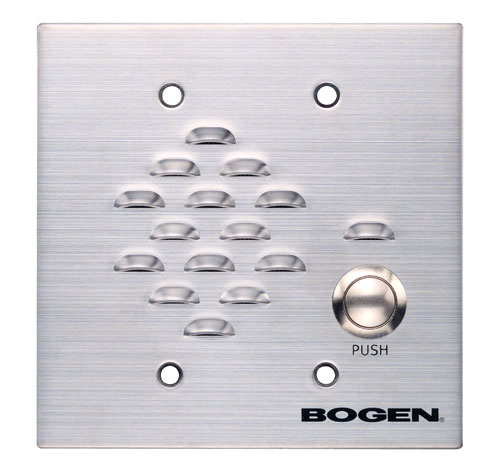
| Bogen ADP1 |
After setting up a doorphone
at my front door on a ringdown circuit that calls me in various
locations when it goes off-hook, it occurred to me that if my front
door had an electric strike plate, I could remotely release the door
using Asterisk.
Not having such a strike plate, I decided to have Asterisk control the
electric garage door opener instead. The garage door is near
enough the front door to serve basically the same purpose as an
electric door striker.
One could, of course, control anything, all the way up to full home automation. Perhaps I'll buy an electric strike plate, they don't seem terribly expensive, although I have no idea how good these are.
The Asterisk configuration is straightforward and involves the specification of a dynamic feature in features.conf. In the [applicationmap] section, I've defined these two dynamic features:
doorcontrol-caller => 5,self/caller,AGI,doorcontrol
doorcontrol-callee => 6,self/callee,AGI,doorcontrol
In the context the door phone is in, I enable the version of this dynamic feature that can only be initiated by the callee:
exten => s,n,Set(DYNAMIC_FEATURES=doorcontrol-callee)
In the context I use to call the doorphone (it auto-answers), I enable
the version of this dynamic feature that can only be initiated by the
caller:
exten => 1109,n,Set(DYNAMIC_FEATURES=doorcontrol-caller)
This way, one cannot take the doorphone off-hook and send the '6' with
a
portable DTMF encoder, only the far end can trigger the doorcontrol AGI
script, regardless of whether the doorphone initiated the call or not.
Unfortunately, two dynamic features cannot share the same
activation code, even if they are used separately. This is mildly
annoying since it means if I call the doorphone, I have to use an
activation code that is different (as you can see, I've selected '5')
than the code I use when the doorphone calls me.
The doorcontrol script is just a bit of PERL that uses Scott Penrose's Device::ParallelPort module to manipulate the D0 line on the parallel port:
#!/usr/bin/perl -w
use Device::ParallelPort;
my $port = Device::ParallelPort->new('parport:0');
$port->set_bit(0, 1); # set D0 high/on
sleep 1;
# wait one
second
$port->set_bit(0, 0); # set D0 low/off
The Device::ParallelPort module requires a /dev/parportX
device node.
I had hoped to get this working with an outboard USB parallel
port interface so that I wouldn't risk damaging the parallel interface
on my motherboard due to a wiring or hardware fault but wasn't
able to figure out how
to properly manipulate the data lines on a /dev/usblpX
device (the ioctl call seems to hang when it should exit, perhaps
looking for an ACK strobe?), if you know how to do this, I'd be
interested in an email to my firstname @ my lastname dot com (see the
bottom of this page for my name). If you
compile your own kernel, you'll have to include Parallel port
support, IEEE 1284 transfer modes, and Support for user-space
parallel port device drivers (under Character devices) to get parallel
port support with /dev/parportX device nodes needed by Device::ParallelPort.
Once this is done, you'll need a hardware interface. I happened to have an extra Clare LBA120
solid-state relay in my parts bin. The Clare solid-state relays
are great because you can drive them right off your TTL data lines
without need of a buffer since they only draw 5mA, which even the most
anemic of parallel ports should be able to source. Not that I
have anything against buffers, but since the parallel port has no +5
line with which to power one, you'd have to pull power from a USB port
or some other such place. The Clares let you keep the complexity
(and spaghetti) to a minimum.
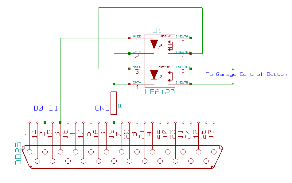
The LBA120 is one Form A relay and one Form B relay operating independently in one 8-pin
DIP. One is
normally-open, and one is normally-closed. I tied both of the
LBA120's control cathodes (pins 2 and 4) to the ground on the parallel
port's pin 19 through a 1k-Ohm resistor to limit parallel port current
draw to a maximum of 5mA. The normally-open relay's control anode
(pin 3) is tied to D0 (the parallel port's pin 2) through
the normally-closed relay. The normally-closed relay's control anode
(pin 1) is tied to
D1 (the parallel port's pin 3). By using the normally-closed
contacts to gate the control of the normally-open contacts, any
common-mode blips in the parallel port data lines, which are typical
when a system is shutting down or performing a POST, will not cause any
false triggering of your external system. We wouldn't want a
reboot or power-cycle to operate the door. Note that you never
have to set D1 as long as your system comes up with it set low/off.
If your system boots with D1 high, you'll have to set it low in
the PERL script. Of course, if you're sure your system will never
send any spurious TTL high signals to D0, you could simplify this by
not using the normally-closed relay at all.
My garage door opener presents 24V to the control switch in my garage
and runs 30mA through its closed contacts. This is well within
the limits of the LBA120 (170mA at 250V). The switches in the
LBA120 introduce about 8.5 ohms resistance, this shouldn't be a problem
though, since garage door control buttons tend to be at the end of
sometimes long runs of relatively thin wire, so an opener won't be
looking for a near-zero-ohm contact closure.
The LBA120 can be had from Mouser Electronics.

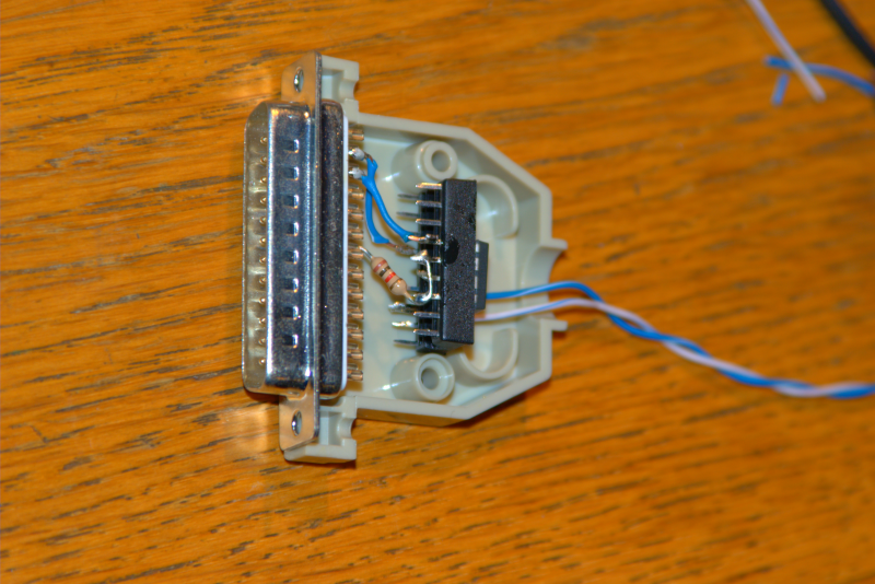
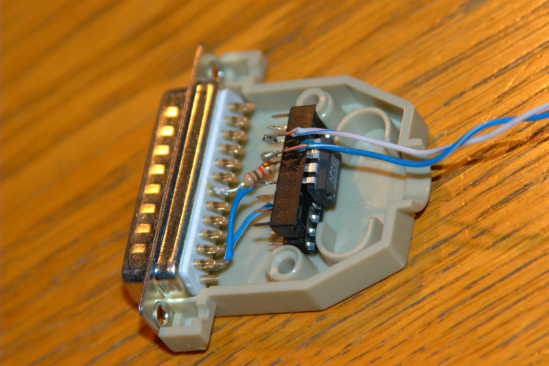
Here are a couple of images of the built circuit. It fits easily
into a standard D shell. Yeah, I know that's an 18-pin DIP
socket. I couldn't find my DIP socket junk box and my local Radio
Shack is badly stocked. The 18-pin actually turned out to work
very well, since it fit perfectly between the screw posts.

The connection between IC pins 3 and 7 consists of bent socket pins and a little solder bridge.
The other side (yeah, I got rosin all over the socket, it's better than using too little and ending up with dry connections.)

Here's some video of it in action.
Last updated February 16, 2008 by Mark Rudholm


